A PLC Splitter (Planar Lightwave Circuit Splitter) represents one of the most critical components in modern fiber optic networks. These sophisticated optical devices divide a single input signal into multiple output signals with minimal loss, enabling efficient broadband connectivity across numerous endpoints simultaneously.
How PLC Splitters Work: The Technical Foundation
At their core, PLC Splitters utilize planar lightwave circuit technology manufactured on silicon wafers through precise photolithographic processes. Unlike traditional splitters, PLC Splitters operate based on optical waveguide principles:
- The incoming optical signal enters through a single fiber
- This signal passes through a carefully designed waveguide structure on a silicon substrate
- The waveguide branches into multiple paths using Y-junction architecture
- Each branch carries an equal portion of the original signal's power
- The divided signals exit through multiple output fibers
This engineering approach delivers remarkably uniform splitting ratios and exceptional reliability compared to older technologies.
Key Types of PLC Splitters for Various Applications
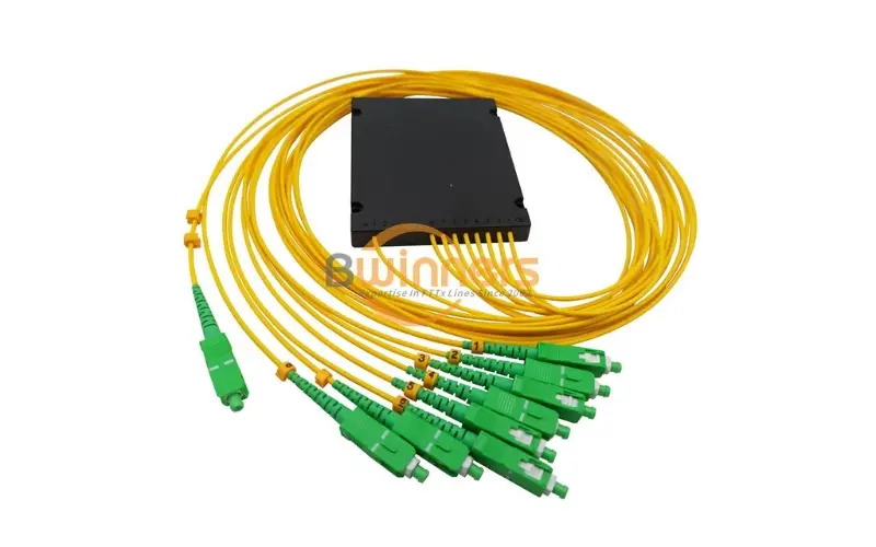
PLC Splitters are available in several configurations to meet different network requirements:
Based on splitting ratio:
- 1×2 (one input to two outputs)
- 1×4 (one input to four outputs)
- 1×8 (one input to eight outputs)
- 1×16 (one input to sixteen outputs)
- 1×32 (one input to thirty-two outputs)
- 1×64 (one input to sixty-four outputs)
Based on connector type:
- SC/APC or SC/UPC connectors
- LC/APC or LC/UPC connectors
- FC/APC or FC/UPC connectors
Based on installation method:
- Rack-mounted PLC Splitters
- Cassette-type PLC Splitters
- Blockless PLC Splitters
Real-World Applications in Telecommunications Infrastructure
Recommended Reading: What is PLC Splitter
PLC Splitters serve as foundational components in multiple telecommunications systems:
Fiber-to-the-Home (FTTH) Networks In FTTH deployments, PLC Splitters enable a single optical line terminal (OLT) to serve multiple subscribers efficiently. A typical implementation might use a 1×32 splitter to connect up to 32 homes using just one feeder fiber, dramatically reducing infrastructure costs.
Passive Optical Networks (PONs) PON architectures rely heavily on PLC Splitters to create point-to-multipoint connections. For example, in a GPON (Gigabit Passive Optical Network), strategically placed 1×8 and 1×4 splitters can create a distribution system serving hundreds of users with minimal active equipment.
Fiber Optic Test Systems Testing and monitoring systems use specialized PLC Splitters to sample optical signals without disrupting service, allowing for continuous network performance analysis.
Advantages and Limitations: A Balanced Analysis
Key Advantages:
- Low insertion loss (typically 7.3 dB for a 1×8 splitter)
- Excellent uniformity across output ports (±0.5 dB)
- High reliability with stable performance across temperature variations (-40°C to +85°C)
- Compact size enabling high-density installations
- Passive operation requiring no power source
Notable Limitations:
- Higher cost compared to fused biconical taper (FBT) splitters
- Limited optical bandwidth compared to some alternative technologies
- Less suitable for applications requiring uneven power distribution
- More complex manufacturing process increasing production time
Selection Criteria for Optimal Network Performance
When selecting a PLC Splitter for your network, consider these essential factors:
- Splitting Ratio: Calculate the number of endpoints needed both currently and for future expansion
- Insertion Loss Budget: Ensure your power budget can accommodate the inherent loss of the splitter
- Connector Types: Match connectors to your existing infrastructure requirements
- Environmental Factors: Consider temperature range, humidity, and installation location
- Wavelength Compatibility: Verify compatibility with your system's operating wavelengths (typically 1310nm, 1490nm, and 1550nm)
Installation and Maintenance Best Practices
Proper installation dramatically affects PLC Splitter performance:
- Maintain minimum bend radius (typically 30mm) for all fiber connections
- Ensure clean connections using proper fiber cleaning techniques
- Install in environmentally controlled enclosures when possible
- Label all ports clearly for future troubleshooting
- Use strain relief for all fiber connections to prevent mechanical stress
- Perform regular insertion loss testing to identify degradation early
Future Trends in PLC Splitter Technology
The evolution of PLC Splitters continues with several emerging developments:
- Integration with wavelength division multiplexing (WDM) technology
- Higher splitting ratios (1×128) for ultra-dense deployments
- Reduced physical footprints for space-constrained installations
- Enhanced environmental hardening for outdoor applications
- Integration with smart monitoring capabilities for remote diagnostics
Conclusion: The Essential Role of PLC Splitters
PLC Splitters remain indispensable components in modern telecommunications infrastructure, balancing cost-effectiveness with performance. As bandwidth demands continue to grow, these precisely engineered optical devices will continue evolving to meet the challenges of next-generation networks.
Understanding the capabilities, limitations, and proper application of PLC Splitters enables network designers to create more efficient, reliable, and scalable fiber optic systems capable of meeting tomorrow's connectivity demands.
Leave a Reply